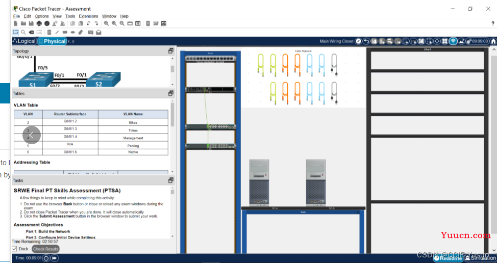
CCNA-应试教育-思科网院-CCNAv7: Switching, Routing, and Wireless Essentials 交换、路由和无线基础。
拓扑 – SRWE 最终 PT 技能评估 (PTSA)

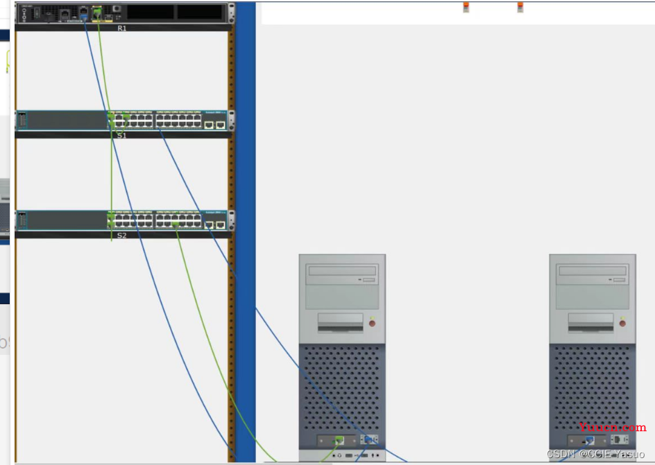
拓扑图这样连
题目
SRWE Final PT Skills Assessment (PTSA)
A few things to keep in mind while completing this activity:
Do not use the browser Back button or close or reload any exam windows during the exam.
Do not close Packet Tracer when you are done. It will close automatically.
Click the Submit Assessment button in the browser window to submit your work.
Assessment Objectives
Part 1: Build the Network
Part 2: Configure Initial Device Settings
Part 3: Configure Network Infrastructure Settings (VLANs, Trunking, EtherChannel)
Part 4: Configure Host Support
Introduction
In this Packet Tracer Skills Assessment (PTSA) you will configure the devices in a small network. You must configure a router, two switches, and two PCs to support both IPv4 and IPv6 connectivity. Your router and switches must also be managed securely. You will configure inter-VLAN routing, DHCP, Etherchannel, and port-security.
All of your tasks will be performed in PT Physical Mode. You will not be able to access the logical topology for this assessment. Network devices must be configured from a direct console connection.
Instructions
Part 1: Build the Network
a. Move the required devices into the equipment rack.
b. Place the PCs on the table.
c. Connect the devices according to the topology diagram.
Part 2: Configure Initial Device Settings
All IOS device configuration must be made through a direct console connections.
Step 1: Configure R1 Basic Settings and Device Hardening
a. Configure basic settings.
           1)   Prevent the router from attempting to resolve incorrectly entered commands as domain names.
           2)   Configure the R1 hostname.
           3)   Configure an appropriate MOTD banner.
b. Configure password security.
           1)   Configure the console password and enable connections.
           2)   Configure an enable secret password.
           3)   Encrypt all clear text passwords.
           4)   Set the minimum length of newly created passwords to 10 characters.
c. Configure SSH.
1) Create an administrative user in the local user database.
= Username: admin
= Encrypted Password: admin1pass
           2)   Configure the domain name as ccna-ptsa.com
           3)   Create an RSA crypto key with a modulus of 1024 bits.
           4)   Ensure that more secure version of SSH will be used.
           5)   Configure the vty lines to authenticate logins against the local user database.
           6)   Configure the vty lines to only accept connections over SSH.
Step 2: Configure router interfaces.
a. Configure R1 with a loopback interface. Configure the loopback0 with IPv4 and IPv6 addressing according to the addressing table.
b. Configure Router Subinterfaces
           1)   Prepare the router to be configured with IPv6 addresses on its interfaces.
           2)   Use the information in the Addressing Table and VLAN Table to configure subinterfaces on R1:
= Interfaces should be configured with IPv4 and IPv6 addressing.
= All addressed interfaces should use fe80::1 as the link local address.
= Use the VLAN table to assign VLAN membership to the subinterfaces.
           3)   Be sure to configure the native VLAN interface.
           4)   Configure descriptions for all interfaces.
Step 3: Configure S1 and S2 with Basic Settings and Device Hardening.
Configuration tasks for the switches S1 and S2 include the following:
a. Â Configure Basic Settings on S1 and S2
           1)   Prevent the switches from attempting to resolve incorrectly entered commands as domain names.int
           2)   Configure the S1 or S2 hostname.
           3)   Configure an appropriate MOTD banner on both switches.
b. Configure Device Hardening on S1 and S2
           1)     Configure the console password and enable connections.
           2)   Configure an enable secret password.
           3)   Encrypt all clear text passwords.
c. Configure SSH on S1 and S2
1) Create an administrative user in the local user database.
= Username: admin
= Password: admin1pass
           2)   Configure the domain name as ccna-ptsa.com
           3)   Create an RSA crypto key with a modulus of 1024 bits.
           4)   Ensure that more secure version of SSH will be used.
           5)   Configure the vty lines to authenticate logins against the local user database.
           6)   Configure the vty lines to accept connections over SSH only.
Step 4: Configure SVIs on S1 and S2
Configure the SVI on both switches.
a. Use the information in the Addressing Table to configure SVIs on S1 and S2 for the Management VLAN.
b. Configure the switch so that the SVI can be reached from other networks over the Management VLAN.
Part 3: Configure Network Infrastructure Settings (VLANs, Trunking, EtherChannel)
On S1 and S2, Configure the following.
Step 1: Configure VLANs and Trunking.
a. Create the VLANs according to the VLAN table.
b. Create 802.1Q VLAN trunks on ports F0/1 and F0/2. On S1, F0/5 should also be configured as a trunk. Use VLAN 6 as the native VLAN.
Step 2: Configure Etherchannel.
Create Layer 2 EtherChannel port group 1 that uses interfaces F0/1 and F0/2 on S1 and S2. Both ends of the channel should negotiate the LACP link.
Step 3: Configure Switchports.
a. On S1, configure the port that is connected to the host with static access mode in VLAN 2.
b. On S2, configure the port that is connected to the host with static access mode in VLAN 3.
c. Configure port security on the S1 and S2 active access ports to accept only three learned MAC addresses.
d. Assign all unused switch ports to VLAN 5 on both switches and shut down the ports.
e. Configure a description on the unused ports that is relevant to their status.
Part 4: Configure Host Support
Step 1: Configure Default Routing on R1
a. Configure an IPv4 default route that uses the Lo0 interface as the exit interface.
b. Configure an IPv6 default route that uses the Lo0 interface as the exit interface.
Step 2: Configure IPv4 DHCP for VLAN 2
a. Â On R1, create a DHCP pool called CCNA-A that consists of the last 10 host addresses in the VLAN 2 subnet only.
b. Configure the correct default gateway address in the pool.
c. Configure the domain name of ccna-a.net.
Step 3: Configure IPv4 DHCP for VLAN 3
a. On R1, create a DHCP pool called CCNA-B that consists of the last 10 host addresses in the VLAN 3 subnet only.
b. Configure the correct default gateway address in the pool.
c. Configure the domain name of ccna-b.net.
Step 4: Configure host computers.
a. Configure the host computers to use DHCP for IPv4 addressing.
b. Statically assign the IPv6 GUA and default gateway addresses using the values in the Addressing Table.
Last Updated: January 2021
Version 1.0
Created in Packet Tracer 8.0 and Marvel 2.0.7
All contents are Copyright © 2021 Cisco Systems, Inc. All rights reserved. This document is Cisco Public Information.
题目翻译
SRWE最终PT技能评估(PTSA)
完成此活动时,请记住以下几点:
检查期间,请勿使用浏览器“后退”按钮或关闭或重新加载任何检查窗口。
完成后不要关闭数据包跟踪器。它将自动关闭。
单击浏览器窗口中的“提交评估”按钮以提交您的工作。
评估目标
第1部分:构建网络
第2部分:配置初始设备设置
第3部分:配置网络基础设施设置(VLAN、中继、EtherChannel)
第4部分:配置主机支持
介绍
在本数据包追踪技能评估(PTSA)中,您将在小型网络中配置设备。您必须配置一个路由器、两个交换机和两台PC,以支持IPv4和IPv6连接。您的路由器和交换机也必须安全管理。您将配置VLAN间路由、DHCP、以太网通道和端口安全。
所有任务将在PT物理模式下执行。您将无法访问此评估的逻辑拓扑。必须通过直接控制台连接配置网络设备。
说明书
第1部分:构建网络
a、 将所需设备移入设备机架。
b、 将电脑放在桌子上。
c、 根据拓扑图连接设备。
第2部分:配置初始设备设置
所有IOS设备配置必须通过直接控制台连接进行。
步骤1:配置R1基本设置和设备强化
a、 配置基本设置。
1) 防止路由器尝试将错误输入的命令解析为域名。
2) 配置R1主机名。
3) 配置适当的MOTD横幅。
b、 配置密码安全性。
1) 配置控制台密码并启用连接。
2) 配置启用密码。
3) 加密所有明文密码。
4) 将新创建的密码的最小长度设置为10个字符。
c、 配置SSH。
1) 在本地用户数据库中创建管理用户。
=用户名:admin
=加密密码:admin1pass
2) 将域名配置为ccna ptsa。通用域名格式
3) 创建模数为1024位的RSA加密密钥。
4) 确保将使用更安全的SSH版本。
5) 配置vty行以根据本地用户数据库验证登录。
6) 将vty线配置为仅接受通过SSH的连接。
步骤2:配置路由器接口。
a、 使用环回接口配置R1。根据寻址表配置具有IPv4和IPv6寻址的环回0。
b、 配置路由器子接口
1) 准备路由器以在其接口上配置IPv6地址。
2) 使用寻址表和VLAN表中的信息配置R1上的子接口:
=接口应配置IPv4和IPv6地址。
=所有寻址接口应使用fe80::1作为链接本地地址。
=使用VLAN表为子接口分配VLAN成员资格。
3) 确保配置本机VLAN接口。
4) 配置所有接口的描述。
步骤3:使用基本设置和设备强化配置S1和S2。
交换机S1和S2的配置任务包括:
a、 在S1和S2上配置基本设置
1) 防止交换机尝试将错误输入的命令解析为域名。整数
2) 配置S1或S2主机名。
3) 在两个交换机上配置适当的MOTD横幅。
b、 在S1和S2上配置设备强化
1) 配置控制台密码并启用连接。
2) 配置启用密码。
3) 加密所有明文密码。
c、 在S1和S2上配置SSH
1) 在本地用户数据库中创建管理用户。
=用户名:admin
=密码:admin1pass
2) 将域名配置为ccna ptsa。通用域名格式
3) 创建模数为1024位的RSA加密密钥。
4) 确保将使用更安全的SSH版本。
5) 配置vty行以根据本地用户数据库验证登录。
6) 将vty线配置为仅接受通过SSH的连接。
步骤4:在S1和S2上配置SVI
在两个交换机上配置SVI。
a、 使用寻址表中的信息为管理VLAN配置S1和S2上的SVI。
b、 配置交换机,以便可以通过管理VLAN从其他网络访问SVI。
第3部分:配置网络基础设施设置(VLAN、中继、EtherChannel)
在S1和S2上,配置以下内容。
步骤1:配置VLAN和中继。
a、 根据VLAN表创建VLAN。
b、 在端口F0/1和F0/2上创建802.1Q VLAN中继。在S1上,F0/5也应配置为中继线。使用VLAN 6作为本机VLAN。
步骤2:配置Etherchannel。
创建使用S1和S2上的接口F0/1和F0/2的第2层EtherChannel端口组1。信道的两端应协商LACP链路。
步骤3:配置交换机端口。
a、 在S1上,使用VLAN 2中的静态访问模式配置连接到主机的端口。
b、 在S2上,使用VLAN 3中的静态访问模式配置连接到主机的端口。
c、 在S1和S2活动接入端口上配置端口安全性,以仅接受三个学习到的MAC地址。
d、 将所有未使用的交换机端口分配给两个交换机上的VLAN 5,并关闭端口。
e、 配置与未使用端口的状态相关的描述。
第4部分:配置主机支持
步骤1:在R1上配置默认路由
a、 配置使用Lo0接口作为出口接口的IPv4默认路由。
b、 配置使用Lo0接口作为出口接口的IPv6默认路由。
步骤2:为VLAN 2配置IPv4 DHCP
a、 在R1上,创建一个名为CCNA-a的DHCP池,该池仅由VLAN 2子网中的最后10个主机地址组成。
b、 在池中配置正确的默认网关地址。
c、 配置ccna-a.net的域名。
步骤3:为VLAN 3配置IPv4 DHCP
a、 在R1上,创建一个名为CCNA-B的DHCP池,该池仅由VLAN 3子网中的最后10个主机地址组成。
b、 在池中配置正确的默认网关地址。
c、 配置ccna-b.net的域名。
步骤4:配置主机。
a、 将主机配置为使用DHCP进行IPv4寻址。
b、 使用Addressing Table中的值静态分配IPv6 GUA和默认网关地址。
上次更新时间:2021 1月
版本1.0
在Packet Tracer 8.0和Marvel 2.0.7中创建
所有内容版权所有©2021 Cisco Systems,Inc.。保留所有权利。本文档为Cisco公共信息。
答案,我不想让你们全部人满分,但是保证肯定过(支持一键copy)
R1
enable
configure terminal
no ip domain lookup
hostname R1
banner motd #Unauthorized Acess is Prohibited#
line console 0
password ciscoconpass
login
exit
enable secret ciscoenpass
service password-encryption
security passwords min-length 10
username admin secret admin1pass
ip domain name ccna-ptsa.com
crypto key generate rsa
1024
ip ssh version 2
line vty 0 15
login local
transport input ssh
exit
interface Loopback 0
description Loopback
ip address 209.165.201.1 255.255.255.224
ipv6 address 2001:db8:acad:209::1/64
ipv6 address fe80::1 link-local
exit
ipv6 unicast-routing
interface g0/0/1.2
encapsulation dot1Q 2
description Bikes
ip address 10.19.8.1 255.255.255.192
ipv6 address 2001:db8:acad:a::1/64
ipv6 address fe80::1 link-local
interface g0/0/1.3
encapsulation dot1Q 3
description Trikes
ip address 10.19.8.65 255.255.255.224
ipv6 address 2001:db8:acad:b::1/64
ipv6 address fe80::1 link-local
interface g0/0/1.4
encapsulation dot1Q 4
description Management
ip address 10.19.8.97 255.255.255.248
ipv6 address 2001:db8:acad:c::1/64
ipv6 address fe80::1 link-local
interface g0/0/1.6
encapsulation dot1Q 6 native
description Native
interface g0/0/1
no shutdown
exit
ip route 0.0.0.0 0.0.0.0 loopback 0
ipv6 route ::/0 loopback 0
ip dhcp excluded-address 10.19.8.1 10.19.8.52
ip dhcp pool CCNA-A
network 10.19.8.0 255.255.255.192
default-router 10.19.8.1
domain-name ccna-a.net
exit
ip dhcp excluded-address 10.19.8.65 10.19.8.84
ip dhcp pool CCNA-B
network 10.19.8.64 255.255.255.224
default-router 10.19.8.65
domain-name ccna-b.net
exit
S1
enable
configure terminal
no ip domain lookup
hostname S1
banner motd #Unauthorized Access is Prohibitted!#
line console 0
password ciscoconpass
login
exit
enable secret ciscoenpass
service password-encryption
username admin secret admin1pass
ip domain name ccna-ptsa.com
crypto key generate rsa
1024
ip ssh version 2
line vty 0 15
login local
transport input ssh
exit
interface vlan 4
ip address 10.19.8.98 255.255.255.248
description Management Interface
no shutdown
exit
ip default-gateway 10.19.8.97
vlan 2
name Bikes
vlan 3
name Trikes
vlan 4
name Management
vlan 5
name Parking
vlan 6
name Native
interface range f0/1-2
switchport mode trunk
switchport trunk native vlan 6
switchport trunk allowed vlan 2, 3, 4, 5, 6
exit
interface f0/5
switchport mode trunk
switchport trunk native vlan 6
switchport trunk allowed vlan 2, 3, 4, 5, 6
exit
interface range f0/1-2
channel-group 1 mode active
interface port-channel 1
exit
interface f0/6
description host
switchport mode access
switchport access vlan 2
switchport port-security
switchport port-security maximum 3
interface range f0/3-4, f0/7-24, g0/1-2
switchport mode access
switchport access vlan 5
description Unused Interfaces
shutdown
S2
enable
configure terminal
no ip domain lookup
hostname S2
banner motd #Unauthorized Access is Prohibitted!#
line console 0
password ciscoconpass
login
exit
enable secret ciscoenpass
service password-encryption
username admin secret admin1pass
ip domain name ccna-ptsa.com
crypto key generate rsa
1024
ip ssh version 2
line vty 0 15
login local
transport input ssh
exit
interface vlan 4
ip address 10.19.8.99 255.255.255.248
description Management Interface
no shutdown
exit
ip default-gateway 10.19.8.97
vlan 2
name Bikes
vlan 3
name Trikes
vlan 4
name Management
vlan 5
name Parking
vlan 6
name Native
interface range f0/1-2
switchport mode trunk
switchport trunk native vlan 6
switchport trunk allowed vlan 2, 3, 4, 5, 6
exit
interface range f0/1-2
channel-group 1 mode active
interface port-channel 1
exit
interface f0/18
switchport mode access
switchport access vlan 3
switchport port-security
switchport port-security maximum 3
interface range f0/3-17, f0/19-24, g0/1-2
switchport mode access
switchport access vlan 5
description Unused Interfaces
shutdown
PCA-PCB
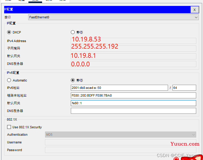
PCA

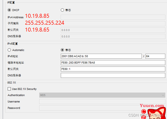
做的时候忘记截图了,只能这样了,一定要严格按照图上面的IP数字,不然就是错的
PCB
